Built the F1 Race Game (Reaction Time & Reflex Tester), a hardware prototype designed to measure human reflex latency in milliseconds. Developed to mitigate the processing latency of high-level operating systems, the firmware architecture was written in AVR Assembly to achieve hardware register control and instruction predictability on the ATmega328P.
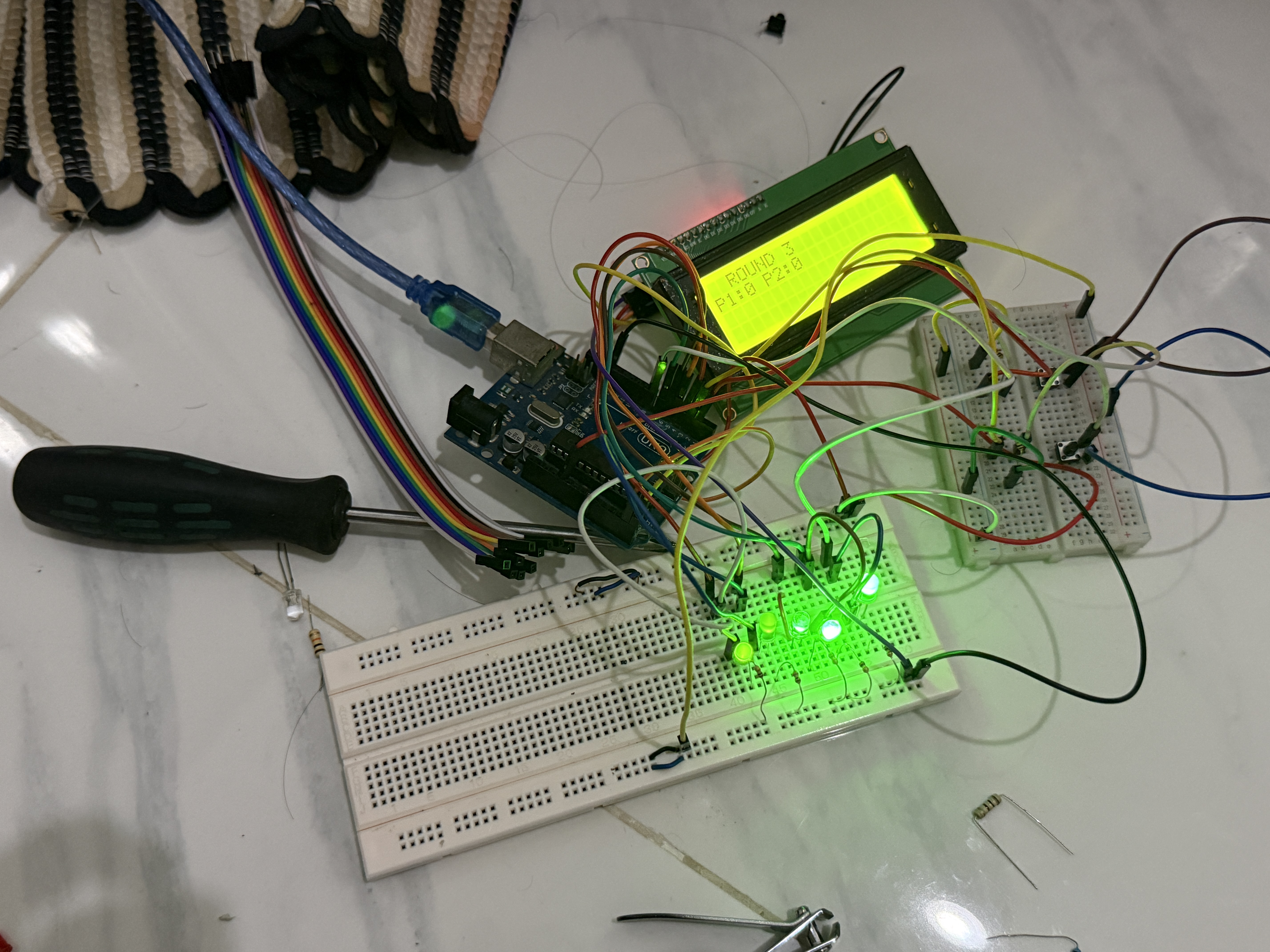
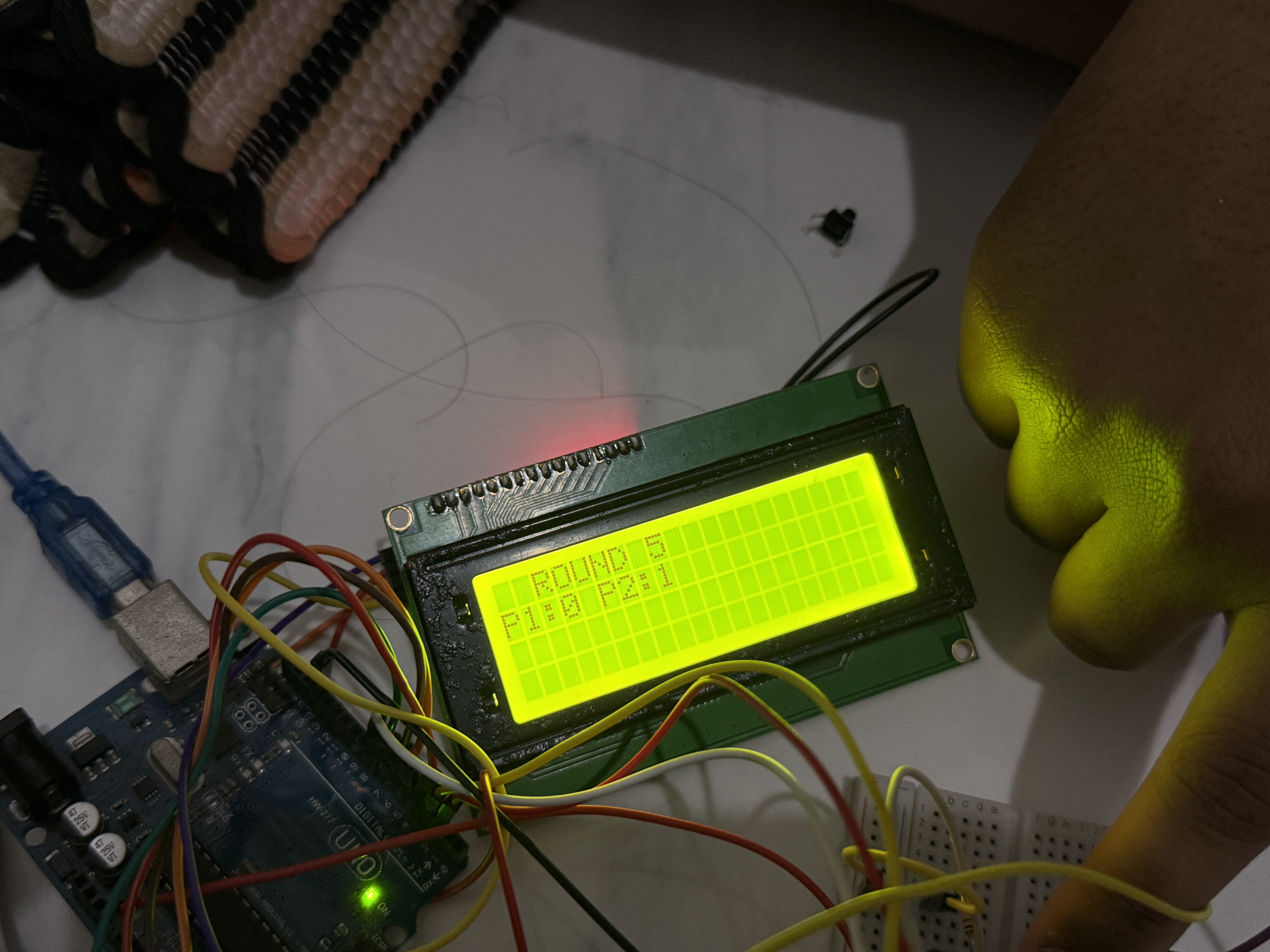
Hardware Architecture
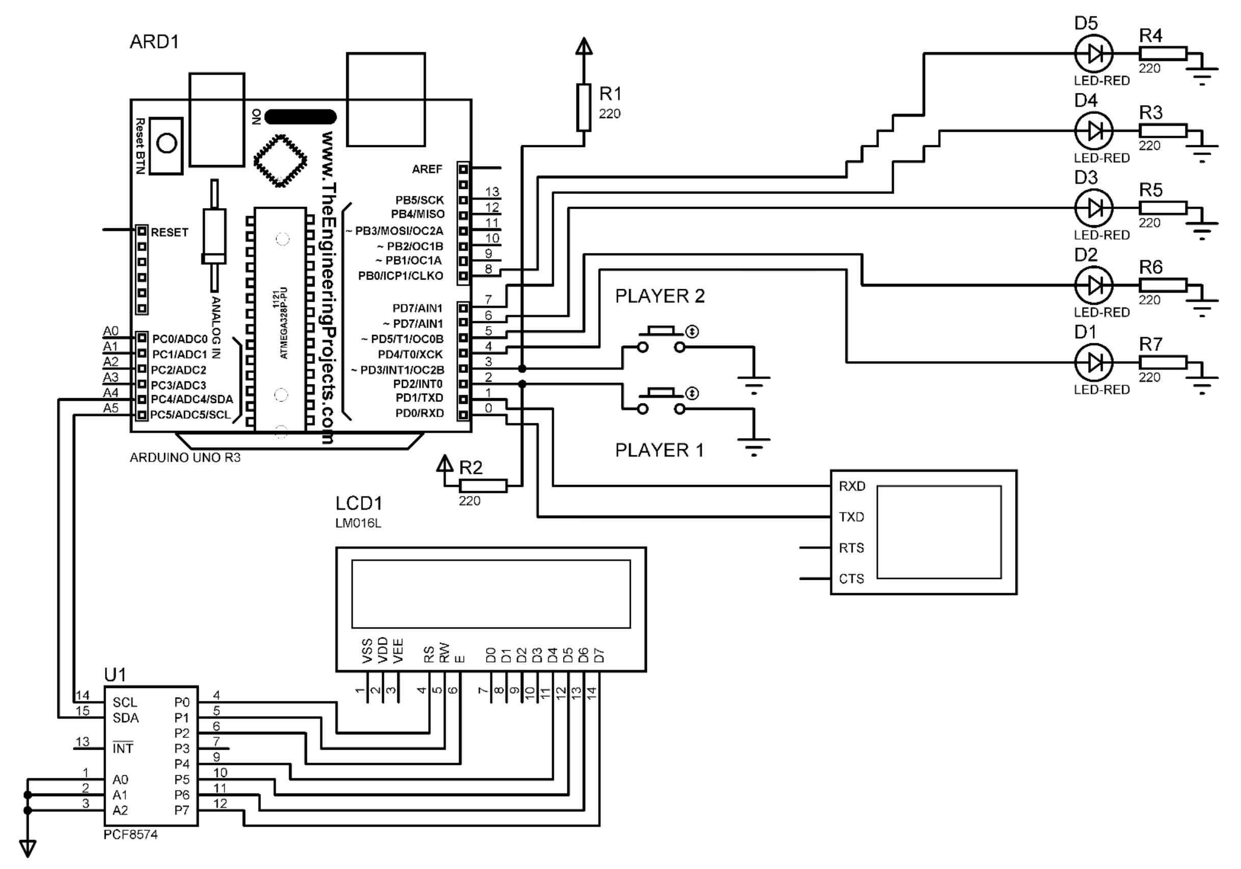
- Microcontroller Unit (MCU): Arduino UNO R3 (ATmega328P).
- Input Interface: Dual Push Buttons via internal pull-up resistors connected to
PD2andPD3. - Output Actuation: Sequenced LED array (
PD4-PD7,PB0) and an Active Buzzer. - Display Interface: LCD 16x2 driven via an I2C Expander (PCF8574) on analog pins
SDA/SCL.
Low-Level Software Implementation & Algorithms
The system integrated six core microcontroller modules using Assembly instructions:
- Timer/Counter (Measurement): Configured Timer 1 in Normal Mode. The elapsed time from visual stimulus to button press was captured by reading the 16-bit
TCNT1register. - Arithmetic Module (16-bit Division): Because the AVR architecture lacks a hardware division instruction, built a 16-bit software division subroutine (
div16_by8) utilizing shift-and-subtract bitwise manipulation to convert raw timer ticks into millisecond values for display. - Input Detection Architecture: Configured polling loops via the
SBISinstruction, bypassing External Interrupts (INT0/INT1) to handle debouncing and False Start detection. - Random Seed Generation (ADC & LFSR): Designed a Linear-Feedback Shift Register (LFSR) algorithm to generate randomized visual delays. The initial seed was extracted by reading analog electrical noise from a floating ADC pin (
A0). - Non-Volatile Storage (EEPROM): Implemented direct EEPROM register control to read, compare, and persist High Score data, setting the
EEMPEbit inEECRbefore each write cycle. - Communication Protocols:
- Wrote a bit-banging I2C driver to transmit ASCII data to the LCD display.
- Configured USART Serial Communication to asynchronously stream real-time data logs to a PC at a 115200 baud rate.
Testing & Verification
- Simulation Verification: Verified I2C addressing (0x27) and UART telemetry via Proteus 8 Professional simulation.
- Physical Prototype Validation: Confirmed computational consistency in the arithmetic module and reliable EEPROM write cycles on the assembled hardware.
Core Competencies
Embedded Systems, AVR Assembly, ATmega328P, Hardware Architecture, I2C Protocol, Digital Arithmetic